|
Meditor
|
Step by step simple tutorial
|
This is a tutorial step by step to obtain a gear like object. Home
address for source code of meditor is:
http://mesheditor.sourceforge.net
After compiled, launch meditor. Assuming you installed meditor correctly
using make install, just update your shell hashtable using -rehash- command
and launch it as: meditor. The current version should fork itself and your system
will process meditor in background automaticaly without to use &
after the command.
The first window launched looks like below and I call it -main window-.
Please, notice there are few indications as view mode, current step for mouse motion, current
layer is 10, three groups of zeroes, and two representations of orthogonal
axis at center and left hand side of window.
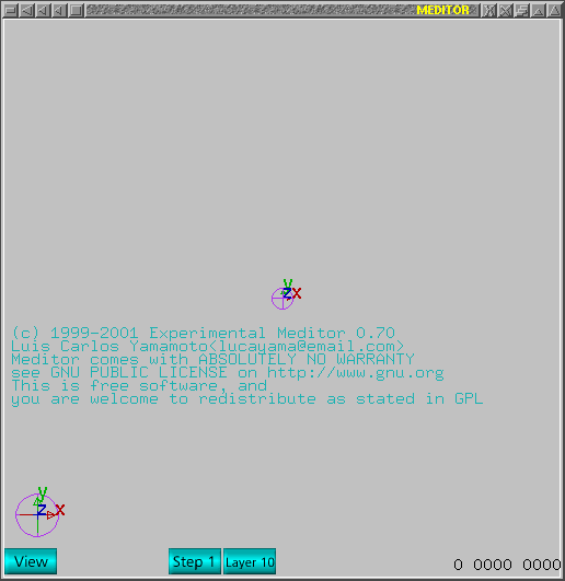 Now, launch command window using 'g' key on main window. Next image is
how the window should look like on screen. Please, notice it has -Objects-
enabled and below all predefined objects appear with labels and buttons.
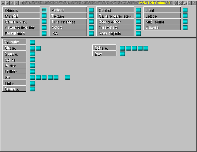 As this is intended to create a gear like object, just push second button
under label -Circle-. The first button is a very simple circle and second
was created for specific target as gears. Notice the numbers changed in
message bar. Now there is one frame and total frames is also one.
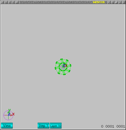 It appears too small to be handled so I zoom in using '-' key several times.
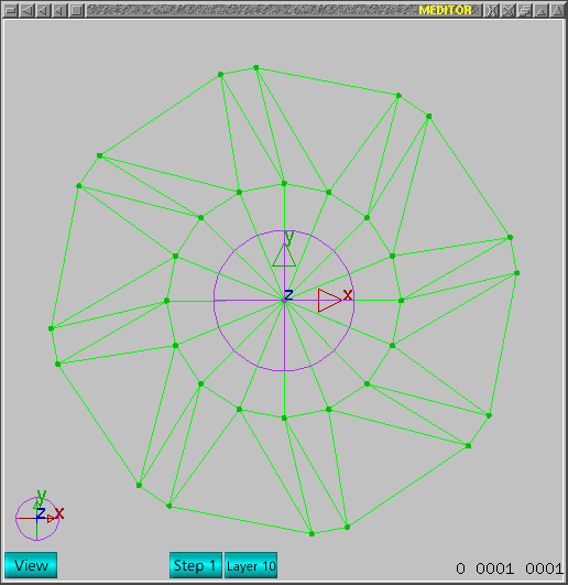 Now enable normals to appear on mesh using 'n' key. First change on mesh
is that to delete unwanted triangles and one can select triangles clicking
at base of normal which appears in yellow. Notice the view mode is view
yet in next window.
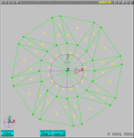 Next step is to change to edit mode. One can use space bar or F3. Space
bar is used to change mode in cyclic way. F1/F2/F3 just jump to VIEW/SELECT/EDIT
modes.
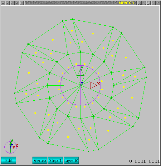 Once -edit mode- is enabled, one should notice it shows -vertex mode- also.
To edit triangles, just push 'END' button to change to -triangle mode- and
'END' button has a cyclic behavior as VERTEX/TRIANGLE/V&TRIANGLE modes.
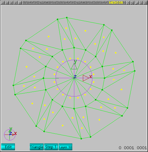 Once the mode is -edit triangle-, one can select triangles and next image
shows all unwanted triangles selected.
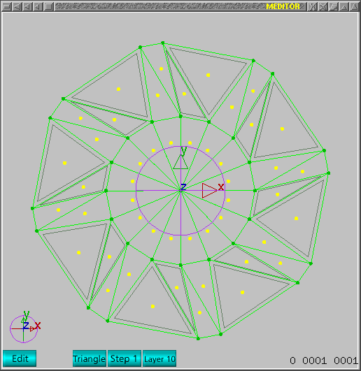 Now use 'delete' key to delete unwanted triangles. This command checks
what mode and looks for selected objects to know what one wants. For edit+triangle
mode, the service selected is delete->selected->triangles.This is
'delete' key, if you try 'backspace' key other service is called. If correct
key was pushed, the window should look like next image.
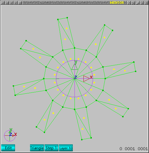 This mesh is completely plane, i.e., for 3D one will need to create -height-
for this mesh. As this need a service called -extrusion-, one will need
to handle points in edit mode, so change using 'END' key and next image shows
correct mode enabled.
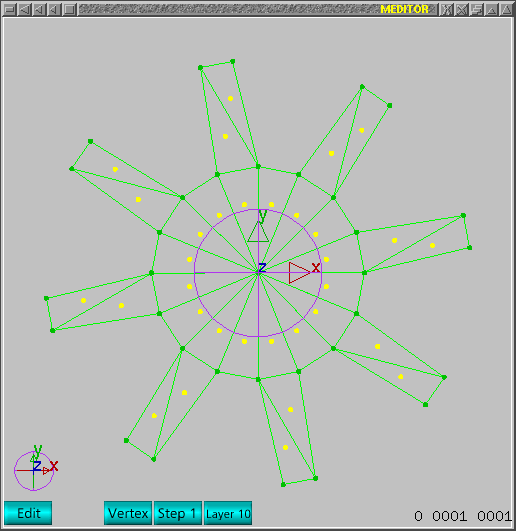 In edit+vertex mode, one can select central vertex and selected vertex
will appear as dark green as in next image.
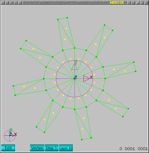 Now one can change view using 'd' key. The default view can be returned
using 'a' key.
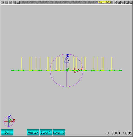 In order to select all points but central point unselected, one can select
the central and use ALT+'enter' to invert selection. Anyway, one can do
the inverse too, i.e., use 'enter' key to select all points and just click
using left hand side mouse button to de-select central point.
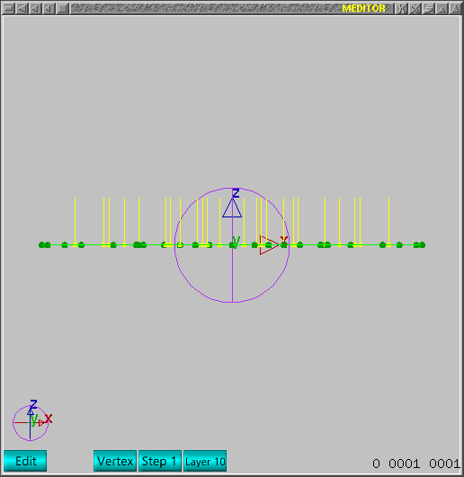 We discarded to use central point to void creation of unwanted triangles.
After selected, one can use 'e' key to call extrusion service for points.
Automatically -move- label will appear and extruded points will follow mouse
motion.
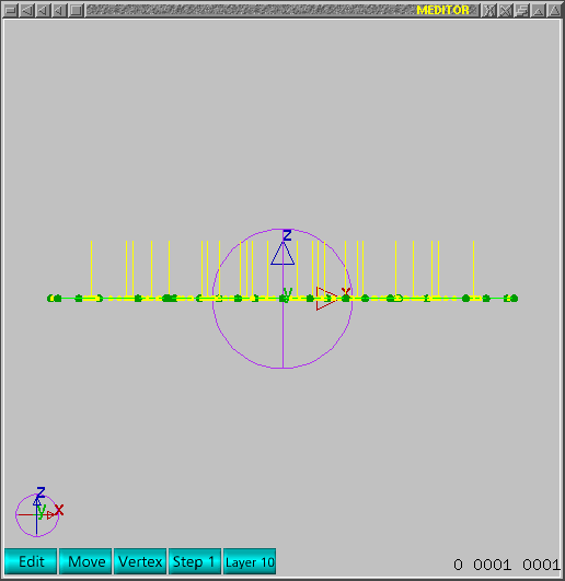 Just move upwards and click left hand side mouse button to stop. Next image
shows how main window should look like.
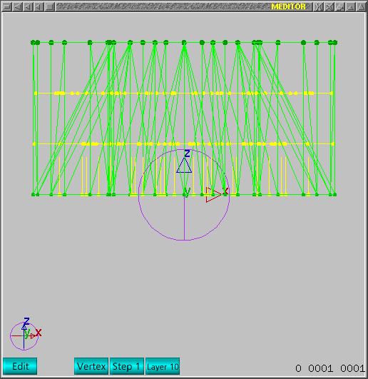 Now change view using 'a' command. Next step is to delete unwanted triangles
created inside the object.
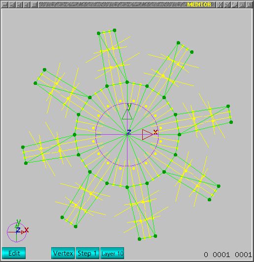 As the process will use services on triangles, one could want to unselect
points. Meditor only use services following mode so one can't delete points
in triangle mode or delete triangles in vertex mode even they are selected.
This is a step to make screen little bit more clear.
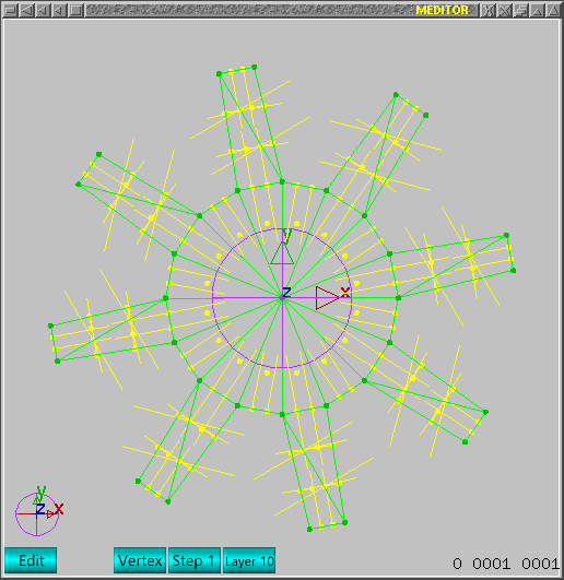 Now change to triangle mode using 'END' key. Notice the next image has
several triangles selected. I indicated using a arrow and selected triangles
are perpendicular to current view so only a very fine dark line appears.
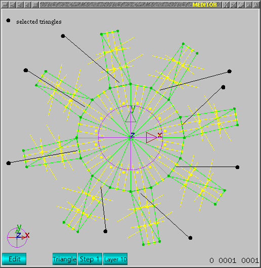 Now delete them using 'delete' key. Again, select other unwanted triangles
as indicated in next image.
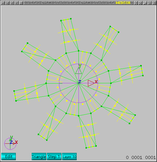
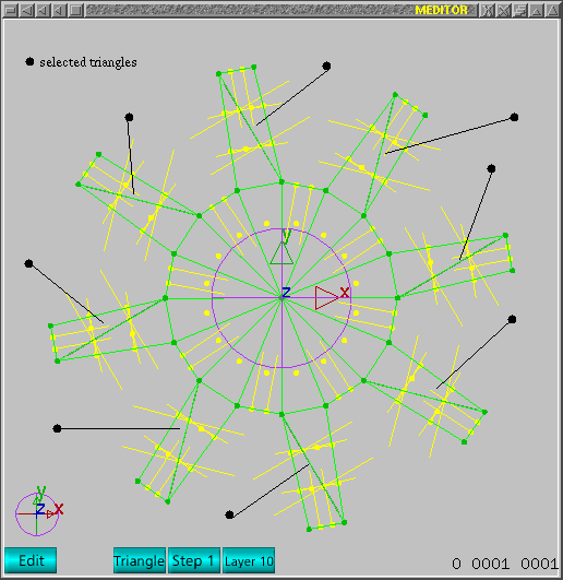 Delete all unwanted triangles using 'delete' key and image should appear
as next image.
 Now change to edit-vertex mode.
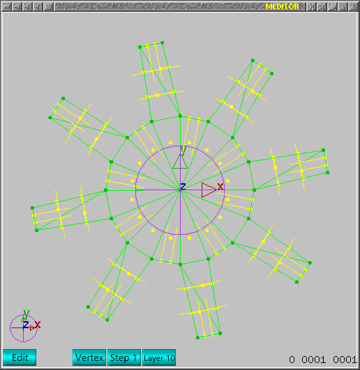 Now one can select the vertex at center as next image.
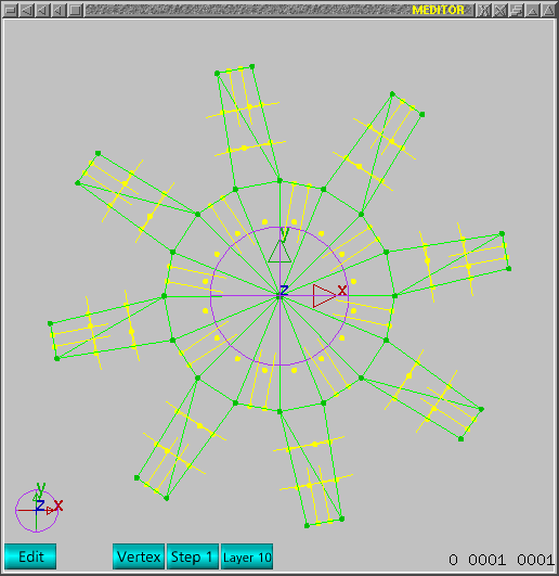 Now change view using 'd' key. The next step is to seal (close a hole)
the extruded points. This is necessary because extrusion only creates lateral
triangles and transversal face is not triangulated automatically.
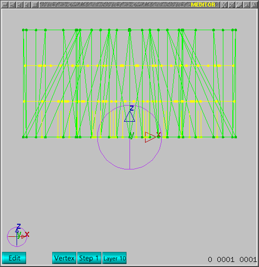 In order to make easier to create new triangles, just make other points
invisible. Select points as next image.
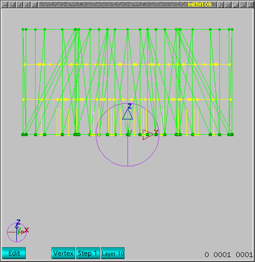 Now just push 'i' key to make them invisible and the mesh should appear
as next image.
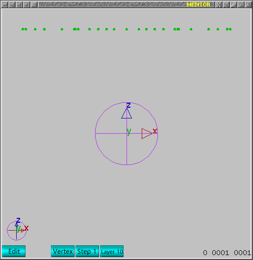 Change view using 'a' key.
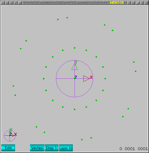 Select all points, as all other are not accessible, one can use 'enter'
key.
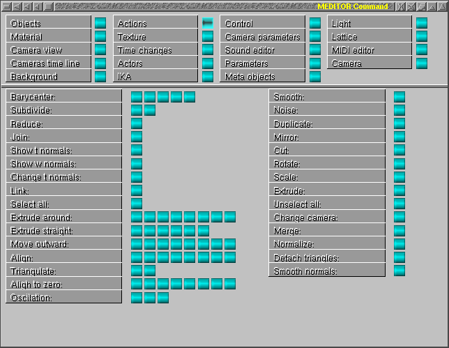
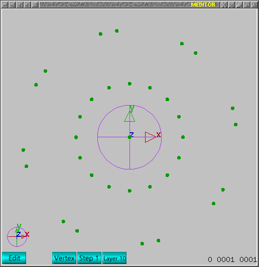 Now the service to triangulate is necessary. One can use 2 methods: triangle.c
(a code) or gts. One can use two buttons under -Triangulate- label corresponding
to that 2 methods.
Push 'backspace key' just to delete duplicated points in selected and select
all again and this voids problems in triangulate methods. Push the second
button (gts) to triangulate those scattered points.
 If all worked, the triangulate surface should appear as next image.
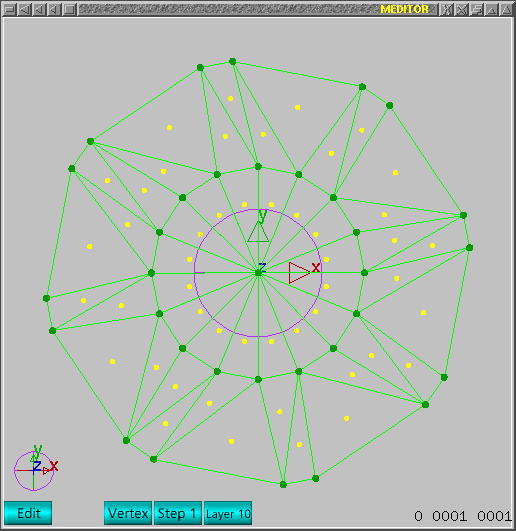 Just unselect all points using 'u' key. Notice there are unwanted triangles
again.
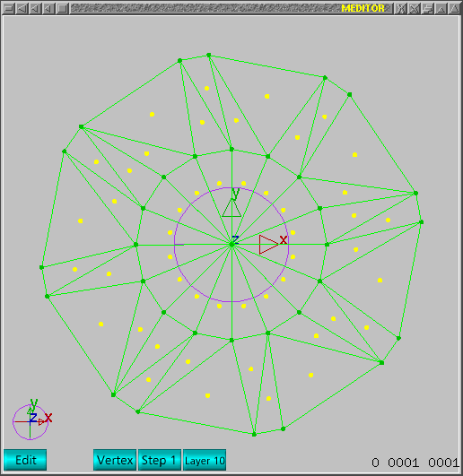 Change to triangle mode using 'END' key.
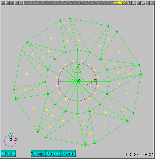 Now select triangles using the yellow points, i.e., just click left
hand side mouse button on yellow buttons.
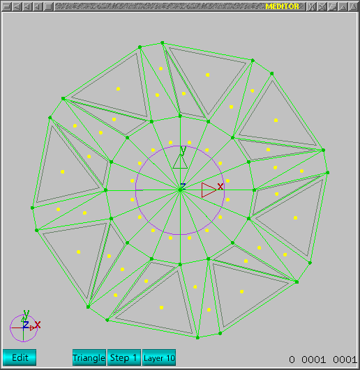 Now one can delete using 'delete' key.
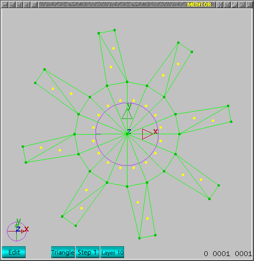 Change view using 'd' key.
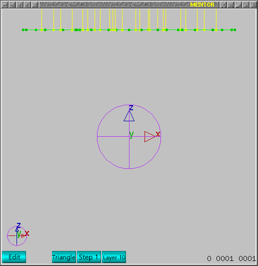 Now change to edit-vertex mode.
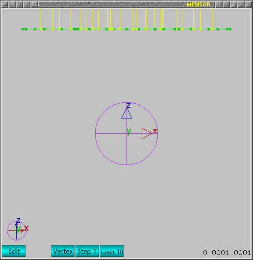 Now one can recover invisible to visible. One can use 'I' key or ALT+'I'
to recover as selected points.
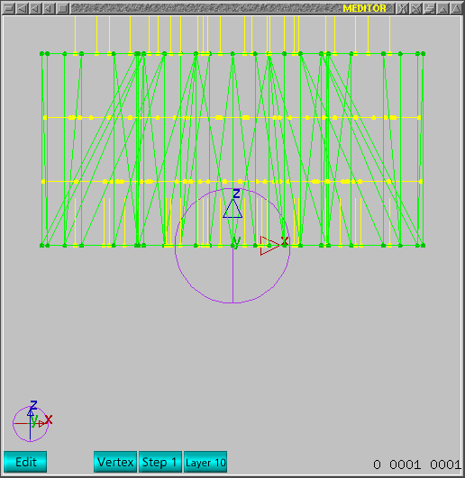 Notice the normals appear bad oriented and one should use 'M' key to try
to correct. If all worked, it should appear as next image.
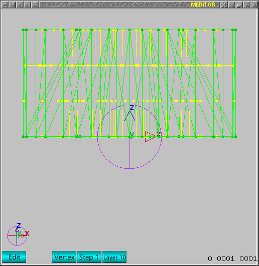 Next step is to create a material to this mesh. On command window, just
push the button labeled as -Material-. Next image should reproduce correct
view.
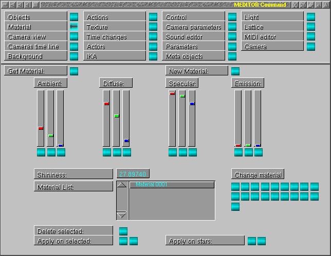
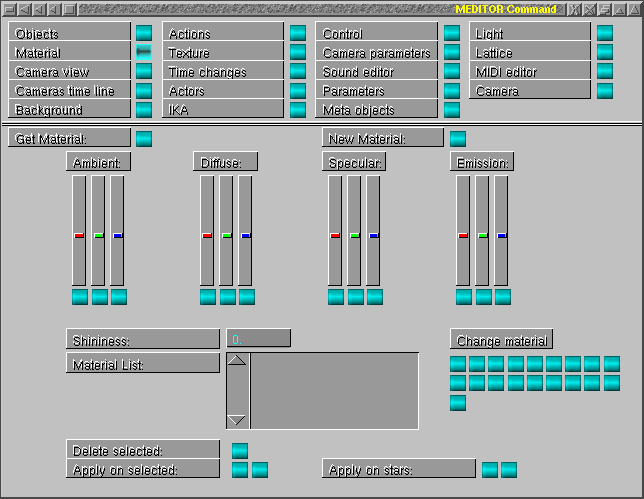 Once one pushes the button labeled as -New Material-, one new material
will appear in material list. One can use pre-defined parameters labeled
under -Change material-. Just push first button from top to bottom and left
to right. Now one can apply on selected mesh. Just push first button labeled
-Apply on selected-. If all worked, next window should reproduce correct view.
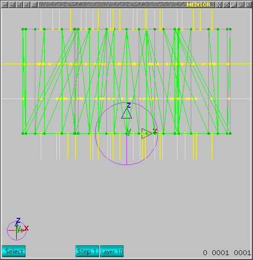
 Nothing changes currently in main window. Now one should use normals pointing
to outward. To correct, just push F2 (Select mode) and push F5. In select
mode, whole object is changed and F5 will call service to invert normal
direction (for selected triangle or whole mesh). If all worked, normals should
appear as next image.
 Now one can use a draft view. ALT+F10 will enable camera following light,
disable wire, and enable fill triangles. If all worked as expected, next
image should reproduce the correct view.
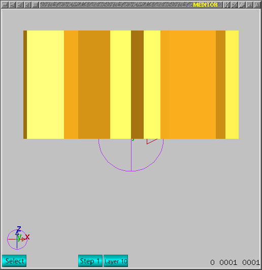 If one wants to play, just hold middle mouse button and move fresh mesh
as next image.
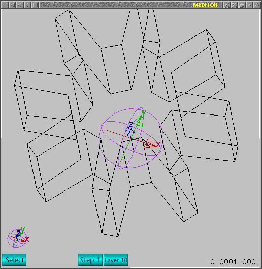
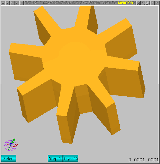 There is a -fast mode- which will show only edges for non-coplanar triangles.
Use 'PAGE_DOWN' key to enable/disable it. Next image shows how it should
look like.
Hints:
1-void double points
2-void internal triangles or T shaped connections for triangles
Those two rules allow to have normals corrected by 'M' command with no problems
mostly.
That is all folks!


